Description
Building Architecture
The total system is composed of
a section within an university building (namely section building 32, 4th
floor of Univ. of Kaiserslautern) with installation (including sensors
and actuators), users, one facility manager and the control system. The
control system is composed of hardware and software components. The building
is influenced by its environment, mainly the weather.
Building Structure

Sections
-
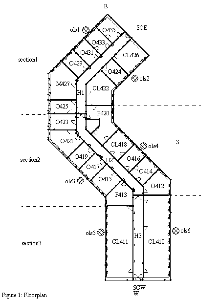
The fourth floor of building 32 consists of
three
sections and shares two staircases SCE and SCW with
other floors of the building, as shown in figure 1.
-
A
section consists of adjacent or separated
groups of rooms, accessible via hallways and/or connecting
doors.
-
Sections are divided into offices (O),
computer
labs (CL), peripheral rooms (P), meeting rooms (M)
and hallways (H).
-
There are three hallways and 22 rooms to control.
Figure 1 also shows the six outdoor light sensors (ols1 - ols6)
and the major compass directions. The sensors cover the six directions
of the different walls. The number in the rooms express the kind and a
unique number.
Rooms
-
Offices (O), computer labs (CL), peripheral rooms
(PR) and meeting rooms (M) are rooms.
-
All rooms in a section are accessible via connected
hallways.
- Offices
-
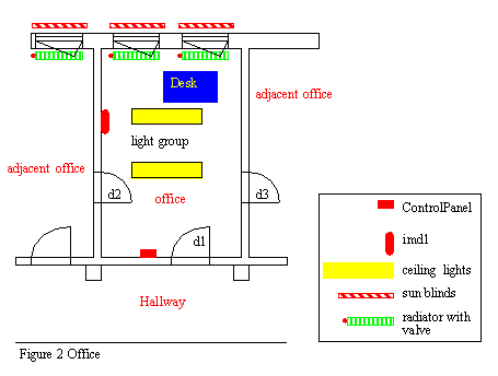
An office (shown in Figure 2) has one door (d1) to
the hallway and can have doors to the adjacent rooms (d2, d3).
-
Only those doors are part of a room that open into
the room. Therefore, d3 is not an object of the shown room, but the name
can be used as a reference.
- Computer Labs
-
A computer lab has one door (d1) to the hallway and
can have doors to the adjacent rooms (d2, d3).
-
The light installation is the same as in the offices.
-
The sensors at the doors are named as before at the
offices.
Each computer lab is equipped with:
-
two status lines (sll1, sll2) that show the
status of the light sources.
- Peripheral Room
-
The lighting of peripheral rooms will not be controlled
by a computer system.
- Meeting Rooms
Hallway
-
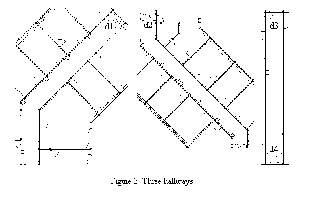
Each hallway is limited by two doors, leading to
the adjacent hallways.
-
Each door is assigned to only one hallway. Therefore,
in the given floor with 3 hallways and 4 doors, there exists one hallway
with two doors and two hallways with only one door.
-
Each door is equipped with a door closed contact,
named dcc<n> , where n is derived from the name of the door.
-
The assignment of the doors and their associated
names are shown in Figure 3.
Each hallway is equipped with:
-
two motion detectors (imd1 and imd2),
placed above the doors at each end of the hallway to determine a person
near a door.
-
one motion detector to cover the whole section (imd3),
actually several motion detectors can be connected in parallel for coverage.
-
one ceiling light group that can be turned on and
off.
-
several wall pushbuttons (pb) to toggle the
light, an impulse relay, which controls the ceiling light group and a normal
relais in parallel to pushbuttons.
-
one status line (sl1) that determines
if the light is "on" or "off".
-
two motion detectors (imd1 and imd2),
placed above the doors at each end of the hallway to determine a person
near a door.
-
one motion detector to cover the whole section (imd3),
actually several motion detectors can be connected in parallel for coverage.
Staircase
-
Staircases connect several floors.
At the floor level, a staircase
is equipped with:
-
one motion detector imd1 above the door to
the adjacent hallway to detect motion near the door.
Sensors for Lighting Control, Heating Control and
Occupancy Detection
-
This section describes the real physical sensors
including converters if necessary.
-
Analog sensors have typically an exponential time
response. Reaction time is the time from a change of the sensed property
to the time when the sensor has reached 90% of the change, excluding conversion
time. Conversion time is the time to convert the analog to a digital value,
that can be accessed by the control system.
-
NC means "normally closed". Closed is coded as "1",
open as "0".
Installed sensors
|
Name
|
Model
Name
|
Type
|
Resolution
|
Range
|
Reaction / Conversion
Time
|
Description
|
Object
Types |
|
wall switch
|
lsw
|
switch
|
|
0, 1
|
10 ms
|
2 stable positions
|
|
|
pushbutton
|
pb
|
momentary pushbutton
|
|
0, 1
|
10 ms
|
1 as long as pushed
|
|
|
outdoor light sensor
|
ols
|
analog light sensor
|
1 lux
|
1 - 10000 lux
|
10 ms / 1 s
|
Mounted perpendicular
to facade,
measures the illuminance
of the facade for the
calculation of light flow through a window.
|
|
| ceiling light sensor |
cls |
analog light sensor |
1 lux |
1 - 1000 lux |
10 ms / 1 s |
Mounted below the ceiling, measures the illumination
of the ceiling as a measure of the average illumination of the room.
(not used by the given system) |
|
| door closed contact |
dcc |
NC-contact |
|
0, 1 |
10 ms |
It is placed above the door and is 1, if the
door is fully closed. |
|
| door open contact |
doc |
NC-contact |
|
0, 1 |
10 ms |
It is placed above the door and is 0, if it is
opened for at least 30 degree. |
|
| door lock contact |
dlc |
NC-contact |
|
0, 1 |
10 ms |
It is placed in the door frame and is 1, if the
lock is closed with a key. |
|
| motion detector |
imd |
passive infrared motion detector |
|
0, 1 |
1 s |
1 means a person is moving, even very slow, in
the range of the detector. |
|
| water temperature sensor |
wts |
analog PWM contact thermometer |
0.1 °C |
0 - 100 °C |
10 s / 160s |
Connected to the incoming and outgoing water
pipes near the radiator. |
|
| room temperature sensor |
rts |
analog PWM air thermometer |
0.1 °C |
-40 - +70 °C |
10 s / 160s |
It measures the room temperature at three points
of the room. |
|
| outdoor temperature sensor |
ots |
analog PWM air thermometer |
0.1 °C |
-40 - +60°C |
120 s /
160 s
|
Mounted in the shadow of the building. |
|
Actuators for Lighting Control and Heating Control
-
Actuators have a linear time response. Reaction time
is therefore defined as the time to change from 0% (100%) to 100% (0%),
if different.
-
One can not expect that actuators are completely
linear over a longer period of time. Position of actuators must therefore
be controlled by using positions known for sure (e.g. "completely closed")
as reference.
-
3-point means three control states: forward, stop,
backward. The actuator moves as long as the forward or backward state is
on. Thus the position can be controlled by the length of time in the two
states, depending on the previous position. End contacts are provided to
stop the motion automatically and to signal the control system.
Installed
Actuators
|
Name
|
Model
Name
|
Type
|
Range
|
Control
|
Reaction Time
|
Description
|
Object
Types |
|
dimmable light
|
sll
|
status line
|
|
0, 1
|
10 ms
|
Senses if the light has
the voltage turned on or off.
|
|
|
cia
|
status line
|
|
0, 1
|
10 ms
|
Even if the CS sends an 1 within
every 60 s, the CS is still alive.
|
|
|
dll
|
dimmer
|
0 - 100%
|
|
10 ms
|
Controls light between 0 (off)
and 10-100% (on).
|
|
|
relais
|
|
|
1, 0
|
|
10 ms
|
|
|
| dimmer |
|
dimmer |
0 - 100% |
analog |
10 ms |
Controls light between 0 (off) and 100% (on).
NOT YET AVAILABLE IN STANDARD ROOM!!! |
|
blind
lifter/rotator |
|
motor |
lift: 0 - 100%
rotate: 0 - 180°
|
3-point |
lift:
120s
rotate:
15s
|
Lets down blind between 0%
(up) and 100% (down). Rotates blind blades between 0 and 180 degrees. At
x degrees light can enter from an angle x degree from vertical. At 0 and
180 degrees the blind is totally closed.
DOWN command sets the angle
to 0° degrees and starts moving down the blinds afterwards.
UP command sets the angle to 180° and
starts moving up afterwards.
All settings are reached by useful combinations
of up- and down commands.
|
|
radiator-
valve |
|
radiator control valve |
0 - 100% |
3-point |
60420 s ??? |
Electrically controlled to open continuously
between 0% and 100%. |
|
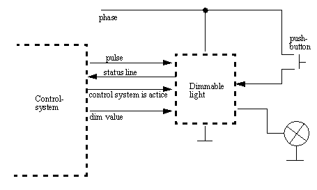
The structure of the dimmable lights
is shown in the next picture. As entries in the dimmable light are the
pulse
line to toggle the light, a
dim value to set the current dim
value and the signal control system is active to show the status
of the control system. If this signal is not send every 60 s, the light
switches to fail safe mode and dim value changes to 100%. The output is
a status line to show the current state (on or off) of the light.
|
|


